|
Column in a vertical position.
This is done at the factory but may need to be
done if shipping or handling was particularly
harsh. The best way to tell is if the disks can't
be placed up and down consistently in the drives
without a 'fade' in or out, or if there is a noticeable
fade one direction while going up and down the
spindles. The column shroud is removed and a small
level is placed on the side of the column (while
it is turned to the different locations) the 4
larger nuts on the studs at the very base of the
column inside at the bottom the machine, are loosened
then retightened so the column is in the best
vertical position it can be.
DO THIS ONLY AS THE LAST ADJUSTMENT
OF THESE THREE!
Drive or tower positioning
for optimum loading and unloading of the drives.
(this would also include placement of a printer.)
The slotted holes that the individual drives are
mounted in can be used, as well as the slight
movement available at the four main mounting screws
of the drive cube.
The towers can be adjusted with the tower extension
stand and the two placement knobs being moved
for optimum placement. Make sure the rubber feet
are removed from the bottom of the tower and that
once the tower is in position the four screws
on the sides of the stand are tightened so it
will stay.
Spindle Location alignment
The symptom for this is that when the pick-arm
stops above spindles it seems to be off in all
the same direction by the same amount (clockwise
or counter-clockwise). And that you can't get
the drives in a good position for loading. Make
sure the CD spindles are securely place on their
locator pins (give them a spin to be sure they
are seated flat)). The spindle locators (white
plastic) can be moved around just a little by
pushing the spindle and sliding the locator around
for best position (The little spindle locator
pegs are on spring loaded over-size holes).
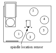
If needed you can change where
the pick-arm stops (Spindle locations) by adjusting
the sensor at the base of the column. Loosen the
two screws through the access holes and move the
black plastic sensor in the middle to the left
or right to get the correct positioning. Try not
to let the sensor go back away from the column,
only left and right. The best way to find the
correct spindle positions is to go to UTILITIES
MENU/LOADER UTILITIES/EXTENDED DIAGS and then
move the pick arm down with the 'pick to spindle'
command then the 'rotate next' and 'rotate previous'
keys. The #1 spindle is the "index"
spindle and doesn't move as much as the rest of
the spindles and should be used as the main one
or index for adjusting for this location, then
move the other spindles for best position. (If
you cannot get the positions to line up correctly
then you must see - column vertical alignment
area)
NOTE: If the load positions
were working fine and the machine wasn't moved
or bumped then it may be just that the sensor
at the base of the column is slightly blocked
- blow out this sensor with air and try the positions
again.
|